Showing posts with label hack. Show all posts

Sunday, March 25, 2007

XBR Chassis, MK1


Heres the latest on the chassis halves, as you can see from the photo the two pieces are nearly finished, the one closest to the camera still needs to be sanded and the sides and tops need fitting. Overall Im happy with the way this first mockup has turned out, this is made from foam construction board glued with liquid nails by selleys.
These weigh less then the same part made from laminated cardboard.

Thursday, March 22, 2007

XBR-001 Mock Up Part 1


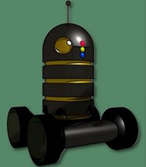
We started laminating the card pieces into structural supports for the chassis today, at this stage we are still trying different ideas to speed construction and reduce costs. this version features three round "bays" for power and motors, with the brain housed in the body on top, the body section is the right height but will feature more rings. The head is just a token shell to judge size but may yet feature a similar under pinning skeleton for the dome structure. Ok, so you need to squint and turn off the lights to see a robot here, but its still early days and we want to document all the steps .

Monday, March 19, 2007

ARMY SEEKS COLABERATORS


With the project stepping up a gear its about time to increase the human factor. It's about time those poor robots got some help taking over the world...
So if you have anything that ou think might be of use to the project be it an idea or design aspect, or even wanting to propose an exsisting system you want to make sure will fit inside, then drop us an email or join the xbr-gag disscussion group and keep up to date on all the goings on.
No idea is too small ( but some may be too big!) so get those ideas out and dust them off. the open source army wants you.....

Sunday, March 18, 2007

The Full Measure (XBR CHASSIS)

XBR-001 chassis dimension final count:

LOWER CHASSIS SECTION

LENGTH: 350mm
WIDTH : 250mm
HEIGHT: 100mm
WALL THICKNESS: 15mm
THROUGH HOLE DIAMETER: 5mm-6mm

INNER SECTION (hardware bay's - C1-C2)

LENGTH: 155mm (including round end)
HEIGHT: 70mm

BODY SECTION (RING X 1):

OUTER RING HEIGHT : 40mm
OUTER RADIUS: 75mm
INNER RING HEIGHT: 10mm
INNER RADIUS: 150mm
CENTER CONDUIT RADIUS: 35mm

HEAD SECTION (DOME STYLE):

HEIGHT: 75mm + (40mm adaptor plate): 115mm
RADIUS: 75mm
EYE RADIUS: 35mm

WHEELS AND SIDE COVERS:

RADIUS: 75mm
WIDTH:50mm *to be confirmed
SIDE COVER IS SAME AS THE CHASSIS PROFILE- without the inner bay cut outs.

Additional infomation and notes.

While the chassis is shown with a 15mm center support, this can be moved in the design stage if you plan to free form the chassis your self. The Chassis is designed mainly as a skid steer robot, but later modules should include other drive options including tracks and Two motor drive with a pivot wheel. The current design would be fabricated from a range of materials including foam, wood or plastic.
These dimensions may change slightly and a half scale version may be produced as well, but if you want to build a smaller one then just scale the plans down.
Today we re drew the basic plans on to thick card and cut out the first run templates for the mock up to be assembled this week. The templates are full scale not half as most of the earlier designs were ( this was to make it easier to design in a normal book, while still keeping it all to scale. The top image is the tools we used for this, A compass, some HB pencils sveral rulers of various lengths , and a digital caliper for taking fine measurments of parts we want to fit in later.
The second image is the cut out templates with a ruler for scale ( in inches ) these templates are all that is needed to draw out the parts needed for the robot, At this stage the hardest part is going to be the dome head, this may be revised from the first renders of the robot, And depending on how hard it is to replicate the dome we may release a diffrent head shape for the first run, but we really like this head.
The wheels are gooing to be a little bigger then first thought, but this increases ground clearance.
Later, hackers.
sprocket.

Sunday, March 11, 2007

When the answer sneaks up and bite's you

Ive been knocking ideas around on the best way to join the head to the body, with out too much extra hardware and not much more tooling when the answer just sort of hit me, "you have already built the solution into the robot" , Yes the four sensor ports in the smaller ring could be used as the head attachment points as well.
So with out having to redisgn the body sections to accomadate the head, the issue has solved it's self, sometimes writing down a description of what your doing works,
I was writing a brief for the part on flickr when it hit me just looking at the ring section.
Score one to the subconcsious .
The wheels are going to get a slight redesign to make them easier to make at home, so less angled sides which are harder to mold.
Two heads will be designed as well , but I hope to develope a later more advanced head and sensor pod for future use ( but thats a long way off)
I hope to release the first prototype blue prints in the next month or so which will give you an idea on the size of the robot.