Monday, March 26, 2007

XBR Mockup system placement test

Heres the first chassis halve with what we expect to house in each section, The cpu will be switchable from slave to master modes to allow the two halves to act as one. The power cell in here is too big and 12volt, we most likely will switch it out for a 9.6 v LIPO cell for remote control planes or cars. The regulator is adjustable to take various power input's and the motors could be switched out to 9 volt high performance units with better gearing from remote control cars.
The two servos on top are for the camera and end effector and a full chassis would have a total of 4 servo ports on the top if the user wanted them. T viper is placed down the side of the battery closest to the camera, you can see the serial port connector sticking out a little from the edge of the chassis ( lower center), The ai2 screen would fit out through the top plate to allow user control, or mounted inside for increased protection during outdoor missions.

Sunday, March 25, 2007

XBR Chassis, MK1


Heres the latest on the chassis halves, as you can see from the photo the two pieces are nearly finished, the one closest to the camera still needs to be sanded and the sides and tops need fitting. Overall Im happy with the way this first mockup has turned out, this is made from foam construction board glued with liquid nails by selleys.
These weigh less then the same part made from laminated cardboard.

Thursday, March 22, 2007

Laminating 101


Here's a quick run down on the laminated pices, First we took five card sections and placed one on top of the other using a layer of contact adhesive between each one, make sure you dont stick it to the bench. Dont worry about the edges just make sure to get a good coating all over the face of the piece right up to the edge but not dripping over it or you will stick it to the press.
Now take the stack and place between two flat mdf or ply boards, place a heavy weight like some water bottles or bricks , around 5-10 kgs is fine depending on the firmness of the dard you use, on top of the pile and leave for around 10 mins , lift off the bricks and leave the board on top overnight to keep flat.
Now do this so you have 4 to six sections depending on how strong you want it to be, or even make up thicker ones with 10 or more layers. but watch the weight.
When its dry, trim the edges of the holes and sides and coat the inside of the corrugated card to reinforce it and help water proof the card, a final coat of glue over the whole pice then hung up to dry will make it last quite a while so your hard work dosent go down the drain.

XBR-001 Mock Up Part 1


We started laminating the card pieces into structural supports for the chassis today, at this stage we are still trying different ideas to speed construction and reduce costs. this version features three round "bays" for power and motors, with the brain housed in the body on top, the body section is the right height but will feature more rings. The head is just a token shell to judge size but may yet feature a similar under pinning skeleton for the dome structure. Ok, so you need to squint and turn off the lights to see a robot here, but its still early days and we want to document all the steps .

Tuesday, March 20, 2007

New POV Renders


We have completed new files for POVray and now the rings are modeled as single entities that are then assembled into the required stacks. As the image shows the discs can be placed in diffrent patterns so robots can easily be identified by moving the colored discs up and down the stack creating unique patterns for identifacation.
The height of the robot can also be changed easily with this desig by adding or omitting rings. THese parts are modeled to scale and will be used in orthographic view to produce detailed CAD renders for input into milling or molding machines.
The design also allows construction from sheet materail and a suitable cutter like a laser or 2 axis mill cutter (CNC)

Stockpile For Mockup

 
Robot Modules
This is part of the pile of boxes we are using to create the first full size mockup , we need around 150-200 cut out pieces for the robot, so its been busy cutting and drawing the last few days.
Posted by Picasa

Monday, March 19, 2007

ARMY SEEKS COLABERATORS


With the project stepping up a gear its about time to increase the human factor. It's about time those poor robots got some help taking over the world...
So if you have anything that ou think might be of use to the project be it an idea or design aspect, or even wanting to propose an exsisting system you want to make sure will fit inside, then drop us an email or join the xbr-gag disscussion group and keep up to date on all the goings on.
No idea is too small ( but some may be too big!) so get those ideas out and dust them off. the open source army wants you.....

Sunday, March 18, 2007

The Full Measure (XBR CHASSIS)

XBR-001 chassis dimension final count:

LOWER CHASSIS SECTION

LENGTH: 350mm
WIDTH : 250mm
HEIGHT: 100mm
WALL THICKNESS: 15mm
THROUGH HOLE DIAMETER: 5mm-6mm

INNER SECTION (hardware bay's - C1-C2)

LENGTH: 155mm (including round end)
HEIGHT: 70mm

BODY SECTION (RING X 1):

OUTER RING HEIGHT : 40mm
OUTER RADIUS: 75mm
INNER RING HEIGHT: 10mm
INNER RADIUS: 150mm
CENTER CONDUIT RADIUS: 35mm

HEAD SECTION (DOME STYLE):

HEIGHT: 75mm + (40mm adaptor plate): 115mm
RADIUS: 75mm
EYE RADIUS: 35mm

WHEELS AND SIDE COVERS:

RADIUS: 75mm
WIDTH:50mm *to be confirmed
SIDE COVER IS SAME AS THE CHASSIS PROFILE- without the inner bay cut outs.

Additional infomation and notes.

While the chassis is shown with a 15mm center support, this can be moved in the design stage if you plan to free form the chassis your self. The Chassis is designed mainly as a skid steer robot, but later modules should include other drive options including tracks and Two motor drive with a pivot wheel. The current design would be fabricated from a range of materials including foam, wood or plastic.
These dimensions may change slightly and a half scale version may be produced as well, but if you want to build a smaller one then just scale the plans down.
Today we re drew the basic plans on to thick card and cut out the first run templates for the mock up to be assembled this week. The templates are full scale not half as most of the earlier designs were ( this was to make it easier to design in a normal book, while still keeping it all to scale. The top image is the tools we used for this, A compass, some HB pencils sveral rulers of various lengths , and a digital caliper for taking fine measurments of parts we want to fit in later.
The second image is the cut out templates with a ruler for scale ( in inches ) these templates are all that is needed to draw out the parts needed for the robot, At this stage the hardest part is going to be the dome head, this may be revised from the first renders of the robot, And depending on how hard it is to replicate the dome we may release a diffrent head shape for the first run, but we really like this head.
The wheels are gooing to be a little bigger then first thought, but this increases ground clearance.
Later, hackers.
sprocket.

Friday, March 16, 2007

Idea Proving Popular


Votes and view over at ideawicket have raised the design to the top of the list for highest ranking, With over two hundred views in under ten days, and an active comments section, its looking well on the robot front.
So if you havent checked out one of the best invention showcasing sites ive found to date, then go take a look and see what the world is creating today.
We have a fewnewmembers at xbr-gag our online message board for all you builders and hackers out there to talk about the next big thing they are up to.
feel free to add links to the Members Sites post, but if you start new posts to external posts we will move the link to this post. thanks for keeping the forums clean :)
See you there.
Go Get GAGED

Thursday, March 15, 2007

Robot Support Network

If your looking to support the growing trend of robotics and the new world order, then you could do worse then buying one of these robot shirts. We are constalntly adding new products including mouse pads, magnets and shirts.

Wednesday, March 14, 2007

XBR Wallpaper Army


This image is for all you robophiles out there who cant wait for the real thing, heres a wallpaper of the XBR robot army getting ready for the first assualt.

Tuesday, March 13, 2007

Robot Blueprint #2a


The images arnt to scale but give all the dimensions needed to re create the chassis sections, (you need two)
So if your looking to see if its going to fit all the goodies you have stock piled for your project download the image and start drawing up the plans yourself.

Monday, March 12, 2007

Creative Commons And The Gag

I have taken a creative commons licence for it , so its free to hack and build, as long as you dont profit and you let people know where the site is and who i am etc.
If you are looking for a project to fund or want to buy the idea for yourself, well email me..
Theres also a link to the xbr-gag disscusion grup, new so no post yet, so had over there and start posting XBR-GAG

Bluprinted Split Chassis


Well instead of talking about it and just looking at the pretty 3D views in the CAD programs, I finally pulled my finger out and commented the fifst view of the XBR chasssis for home use :)
This is the simplified version designed to made from either foam and wood or plastic molding, or even aluminum casting if you have the gear.


The dimensions and axel points will give you an idea on scale and ill try to see if i can get the image scaled to the right size for printing at a4 size. The idea is too create a basic shape and size constraint for the designers to work within and a simple uniform adaptor system for add on parts.
This simplifies design and build time as well as cost and tooling times for large run production.
The details for pin layout etc can be copy pasted from one cad file to the next resaulting in quick and easy redesign of the whole robot, as well as new parts being made that still fit everything you already have.
Backwards compatiablity is something that we want so parts dont become obsolete, rather just wear out from over use :)
thats enough rambling for now, later guys.
Simplified design of the last chassis shape

Sunday, March 11, 2007

When the answer sneaks up and bite's you

Ive been knocking ideas around on the best way to join the head to the body, with out too much extra hardware and not much more tooling when the answer just sort of hit me, "you have already built the solution into the robot" , Yes the four sensor ports in the smaller ring could be used as the head attachment points as well.
So with out having to redisgn the body sections to accomadate the head, the issue has solved it's self, sometimes writing down a description of what your doing works,
I was writing a brief for the part on flickr when it hit me just looking at the ring section.
Score one to the subconcsious .
The wheels are going to get a slight redesign to make them easier to make at home, so less angled sides which are harder to mold.
Two heads will be designed as well , but I hope to develope a later more advanced head and sensor pod for future use ( but thats a long way off)
I hope to release the first prototype blue prints in the next month or so which will give you an idea on the size of the robot.

Split chassis design #2a


The image shows the latest design step for the lower chassis, It features a simpler design that could be moulded in a single part mould , in plastic or aluminum casting.
The wheels that we have designed have holes in them that line up with the chassis screw holes, so the sidecovers can be removed from the robot with out undoing the wheels. The body can be used either as it is or with the body section in place by drilling some mounting holes in the chassis.
This is just one design that we are working on, with a second more developed chassis that would require a more complex multi part mold or milling is also in design.
The project is likely to spawn two projects, One would be a chassis for full run production, if we reach that stage with this design. And the second is an Open source design that can be used to make your own chassis for home use.
I suppose the main reason for doing this is to get peolpe thinking about the aesthics of robotics rather then just the function. So if your building a robot, at least try to add a body istead of just metal frames and screws.
sprocket2cog

Friday, March 9, 2007

Project Update

Ok, So we havent been at this project for that long, but as always if your diligent you will have noticed that at every stage you can find something to fix...We did.
And what have we found in the first week of intensive design and research ?
well to make it easy Lets list them now,
  1. No matter how much you think you have looked, you havent found all the robot sites and companys out there.
  2. Some free cad programs are actually really good.
  3. Online machinging is expensive
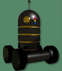
  4. If you just design a body, people think its not a real robot.
  5. Domes for the head are going to be harder to get machined
  6. Extrusion designs, while cheap to mass produce, cost heaps for the tooling
  7. Mirroring parts saves money in both tooling and production run number.
  8. Dont overlook The fastening systems for your parts, can you reach them to tighten them up? Are the screws strong enough? that sort of thing
  9. Dont over think the solutions, sometimes the first thing you think of is the best one to use, most times its not and you will wish you hadent started but dont be afraid to try the simple ideas first.
  10. Unless you plan to make minimum runs of over 500 uunits of each part, dont bother with the bigger companies, high overheads etc increase the tooling cost for extrusions and mouldings. So unless its a big order needed in a hurry, try CNC milling or home fabricatioon techniques first. ( unless you got a lot of money to waste)
  11. Dont overlook the thickness of the work, dont carve out so much that it weakens the shell beyond acceptable levels.
Well that just about cover's it. Now we have to do a basic head and wheel design. Then refine the whole lot with all the finnishing touches. Then a half size replica of the parts will be hand formed from wood and polystyrene this will be used to visualize the bot overall ,as well as to work out new part and add on designs like arms and new heads.
We have a lot to do and this project may never go in to full production. But if not we still make small numbers of hand made units in plastic for sale to hobbiest's and collectors.
We are going to try to get a few more people on board at a later date to help design and program the brain for a example robot. But as pointed out earlier. We are not trying to build a fully functional robot here. We are constructing a shell that can be repurposed to suit the end use.
Add a camera and remote control for a security robot.
Add an mp3 player and speakers for a boom box robot...arms and shotgun for a bomb disposel droid :P that sort of thing.
And the next stage will included a removeable system tray so redeployment as a new robot can be really easy, just unplug and slide out the tray and sensor pod, then slide in the new bench tested brains for a whole new robot function, switch the head for a new look, or take out the body sections to decrease the height for resuce work in confined space's
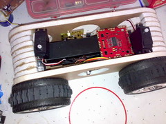
Thursday, March 8, 2007

Chassis (cad001b)


The second concept using the same design as the first but with major refinement.

Now inclludes sensor slots, Threaded body adaptor ring for joining body sections to the base with threaded rod, Increased ribbing on the floor to reinforce the side cover screw holes and with the adaptor ring moulded seperately from the body, the main chassis section could be extrusion moulded on a smaller scale ( 1:2) in nylon for corrosive enviroments or mass productionfor childrens toys.
Crystal clear acrylic extrusions could also be cast for internal viewing of the robots components for school and hobbie applications.
EXTRUSION EXAMPLE

Lower Chassis (cad-001a)


The lower chassis design while appearing to be simple actually will be the hardest to design.
This first concept is designed to give the developers a chance to see the problems faced with the two half construction technique we are employing for this part.
Vertical split cranckcases have been used for many years now, and as our intent is not to hold oil in, but to keep dirt out, we feel that this system will allow the right mix of modular design and easy assembly, while not sacrificing strength and should with the right gaskets be fairly water resistant as well.
This 3d view shows the need for more screw holes for the two halves as well as locater pins and more internal bracing to increase functionality and strength.
The curved ends allow the bot to navigate higher terrain then an un bevelled edge and makes the robot pleasing to look at.
Extra work yet has to done on the body location and support substructure, At the moment there is no way to secure the body without screwing it to the chassis. This ist an ideal solution so further dwvwlopment in this area is also foreseen.

A Good Wicket


I recevied an invitation today in my inbox from a beta site called ideawicket.
This site allows you to showcase your project and inventions and is squarely aimed at new innovator's and inventors, as well as the bigger companies who want more pupli exposure for new ideas and projects.
You can add section details for costing and market deployment avenue's as well as experiance and interlectual content and a few more to inform others of what your up to.
And can also add a video feed and images to the page.
A market to companies button rounds off the site nicely allowing you to showcase your ideas even further.
So check out the infomation for the robot HERE as well.

Body Ring prototype (cad-01a)


First design for the main stay of the body ring system.
Pin locator's and matched wiring ducts running though the ring allow interlocking of the rings to allow a stronger design and make it easier to line up the internal ports, this will minimize cable damage during assembly of the chassis.

Features

  • Modular design
  • rounded edges for comfort and improved appearance
  • Multi direction sensor ports
  • Reconfigurable design that allows easy breakdown and reassembly
  • Ability to resized and fabricated to suit many applications using a range of techniques and materials, including nylon, aluminium and acrylic plastic
  • Durable and cost effective design
Further development of these section's will allow for increased usage with more sensors and other options like servo mount rings for arms and side pods.

Tuesday, March 6, 2007

Online Prototyping


This is a site we will be most likely using during the first stages of prototyping the robot, The aim is to supply a robot chassis with wheels and gearboxes installed ready for the motors and control systems, which may be offered in the future.
The blow mould body casing will still be made locally, but other smaller parts like gears and mountings may be made at a facility that can handle the many challenges we expect to face.
So if your after a way to get your ideas a reality, head over to,
http://www.emachineshop.com/index.htm
and download the free software and get cracking.

Monday, March 5, 2007

SCALE IT UP


To give you an idea on scale , i've included this picture of an early design sketch. The overall height is around 40-45 cm with the base section being about 26 X 20 X 6 cm , and the main body section being about 15cm in diameter.
We are currently in discussion's to decide the final construction technique and materials, and hope to finalize a manufactor for the inital prototype this month.
We are also sourcing DC 12 v motors for the robot and hope to secure a local supplier for these parts.
Stay tuned as we develop the chassis over the next few months.

FIRST LOOK


Well S2c is about to move into the robot body making market with the design and research stage already under way with the aim of producing a low cost, plastic shell for deployment on a number of robot drive systems.
These shells will include the lower chassis with option's for motors and other systems to be added as we aquire more funds and resources.
The first run will likely include two gearhead motors and a simple control interface for some out of the box use, But will ultimately requirethe enduser to ad thier own control and brain systems to the robot, motor upgrades arent out of the question with blank shells also being available for purchase at a later date.
any ideas or feedbackcan be directed to the team at sprocket2cog@gmail.com for further evaluation.
We hope to one day be able to provide full robotics systems to our customers not just bodies and shells, but for now we aim to provide a cost effective solution to upgrading your robot.